Trackplan and Wiring
Transfer the trackplan on plywood and start wiring the DCC and DC buses
Trackplan
I used masking tape to transfer the trackplan onto the plywood base, then started wiring the DCC and accessory DC buses.
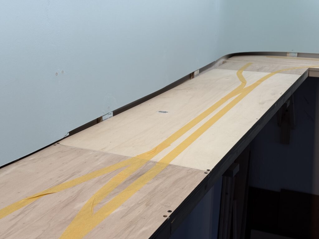
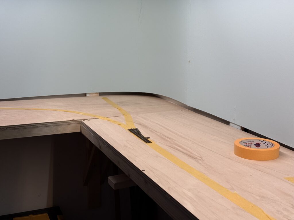
What works on paper doesn’t necessarily translate well to the layout. I like to use masking tape to sketch a rough version of the trackplan directly on the plywood subroadbed, allowing me to test-fit curves, sidings and spurs.
Wiring
There are three main buses running under the layout:
- DCC bus, using 2.5mm² wires (14 AWG)
- 12VC DC bus for Tortoise switch machines, using 0.75mm² wires (18 AWG)
- 12VC DC bus for lighting, including streetlights and structure lights, using 0.75mm² wires (18 AWG)
I flipped the plywood base and started fixing the bus wires in a temporary, untidy manner. I will clean up the wiring once all the track feeders and Tortoise switch machines are installed, so that I can determine the correct length for each wire.
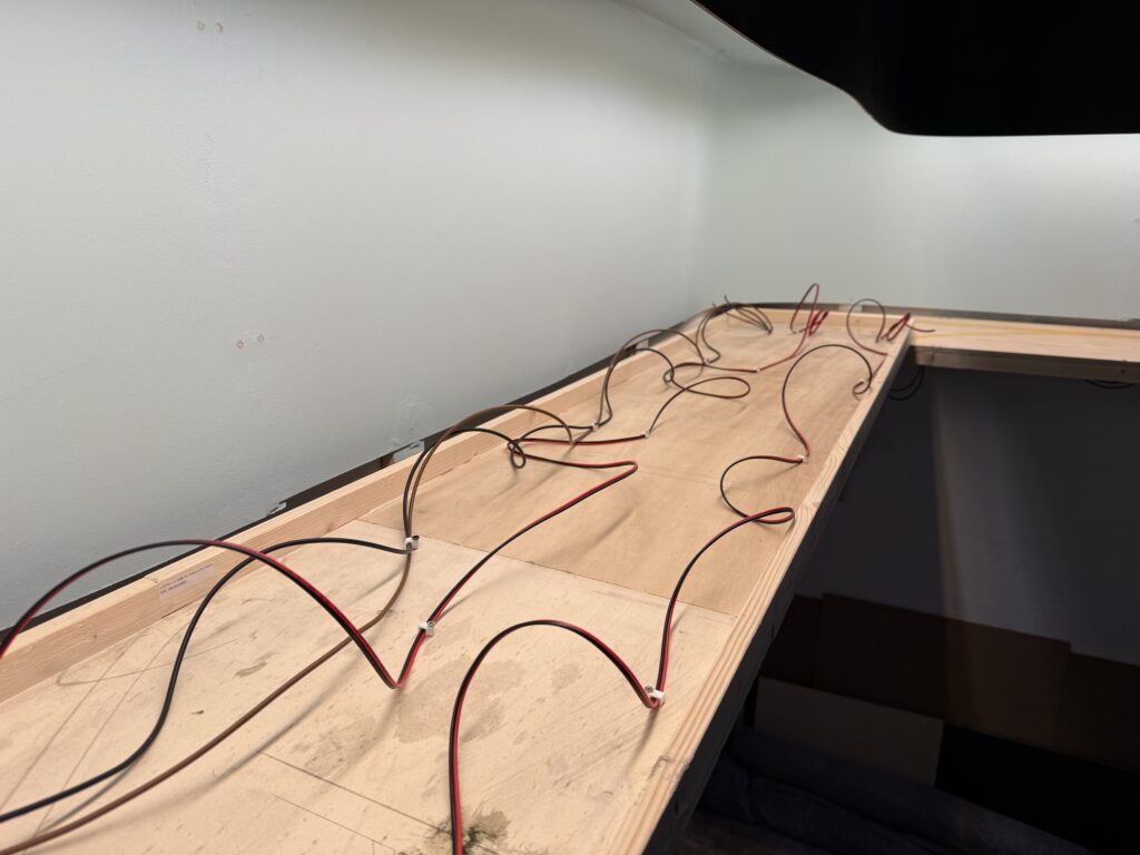
To tap power without cutting or stripping main wires, I used suitcase connectors – quick, reliable, and ideal for temporary setups. They let me add feeders or accessories on the fly, which is perfect while I’m still fine-tuning the layout.
This approach saves time now and prevents headaches later when the layout is more complete.
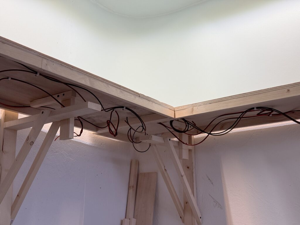
Wiring the layout with DCC and accessory power requires both solid planning and a bit of foresight. I installed a robust DCC bus using heavy-gauge wire for consistent power delivery, with feeders soldered in regularly to avoid voltage drops.
Accessory wiring, like 12V DC lines for Tortoise machines and lighting, runs separately for clarity and ease of troubleshooting.
While the system is built to be dependable, I’ve allowed for future adjustments – leaving a bit of slack, labeling connections, and routing wires with accessibility in mind. Layouts evolve, and the wiring can too.


